Getting Started with FoBE Mesh Tracker C1
Introduction
FoBE Mesh Tracker C1 is a fully integrated application board for outdoor LoRa communication. It integrates an nRF52840 MCU, GPS, buzzer, OLED display, and a LoRa transceiver, providing everything needed for an outdoor LoRa device.
The board features a rotary encoder, one user button, one reset button, an onboard BLE antenna for convenient configuration, two indicator LEDs, a USB-C connector, reserved SWDIO/SWCLK header pads, an 8-pin expansion header exposing 6 GPIOs, and two UF.L connectors for the LoRa and GPS antennas.
Key Features
-
Core Components
- nRF52840 MCU
- GPS module with UF.L antenna connector
- LoRa transceiver with UF.L antenna connector
- 0.96-inch OLED screen
- Buzzer for audio feedback
-
User Interface
- Rotary encoder for easy navigation
- One user button and one reset button
- Two indicator LEDs
- Onboard BLE antenna
-
Connectivity and Expansion
- USB-C connector
- Reserved SWDIO/SWCLK header pads
- 8-pin header exposing 6 GPIO pins for external expansion
- 2-pin MX1.25 battery input interface
- Two 6-pin SH1.0 FPC connectors for external modules
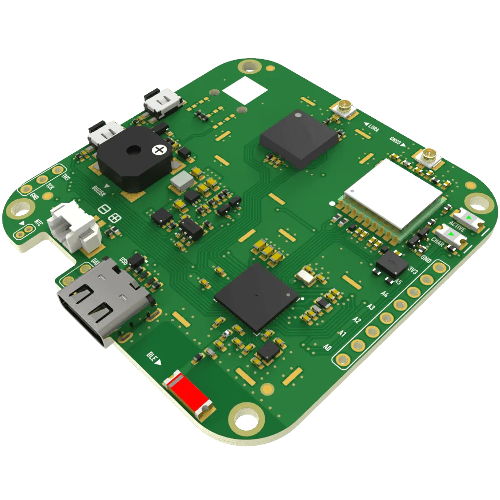
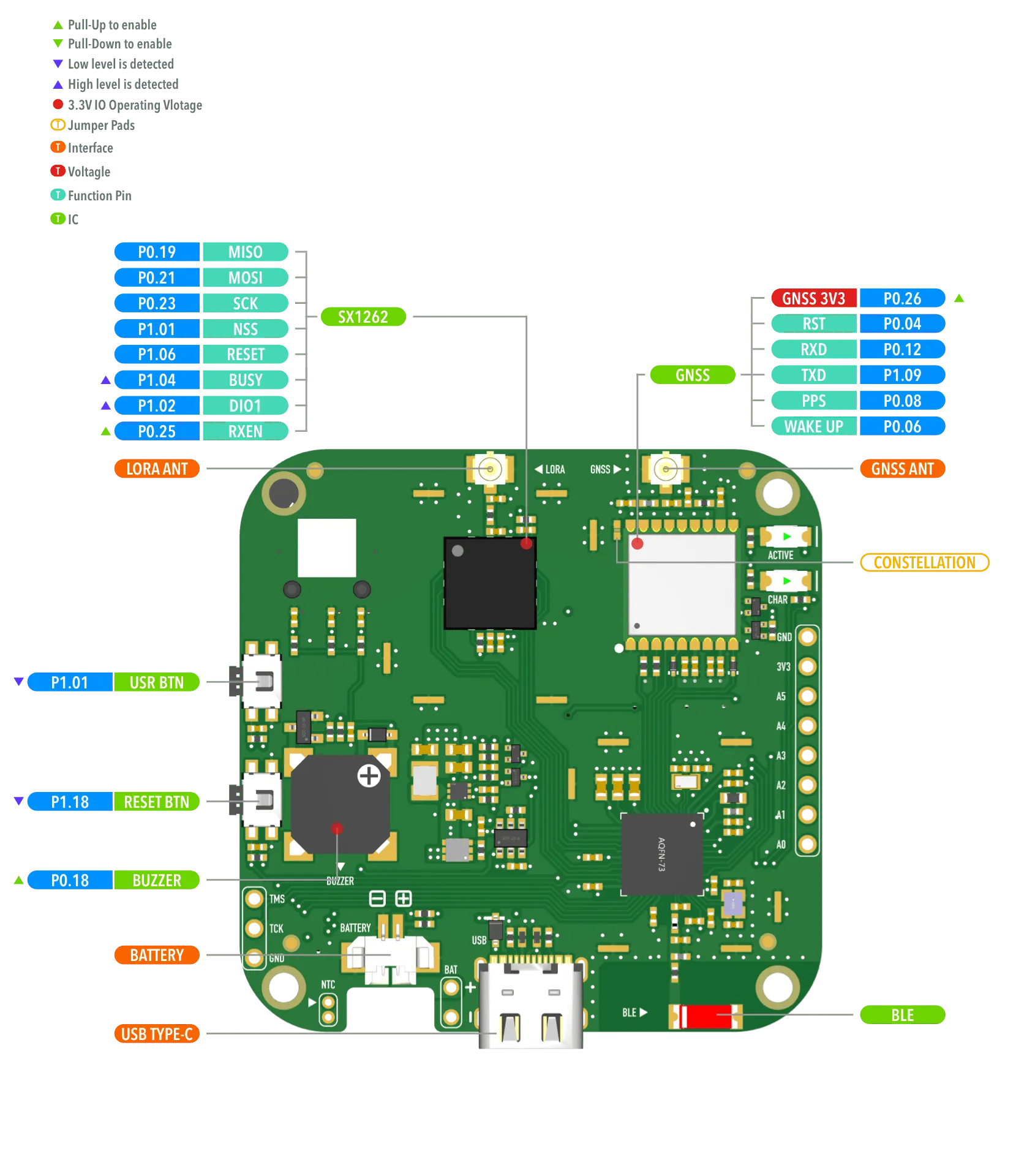
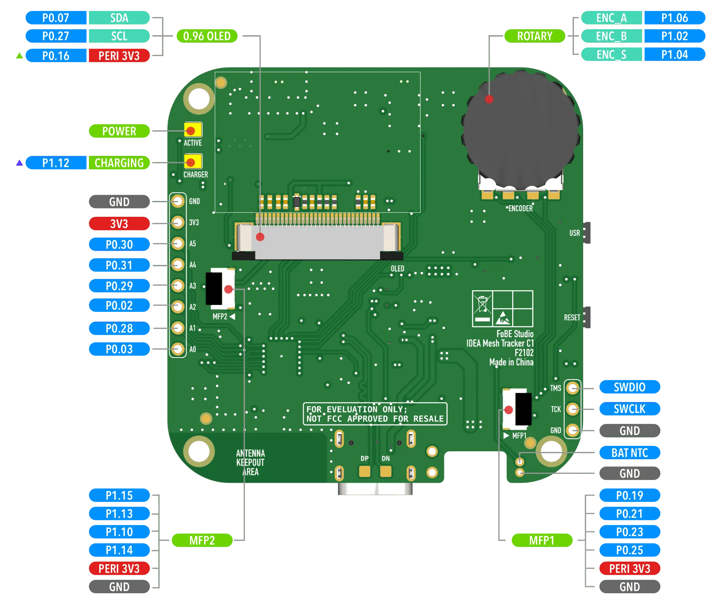
Hardware diagram
The following figures show the FoBE Mesh Tracker C1 hardware diagrams.
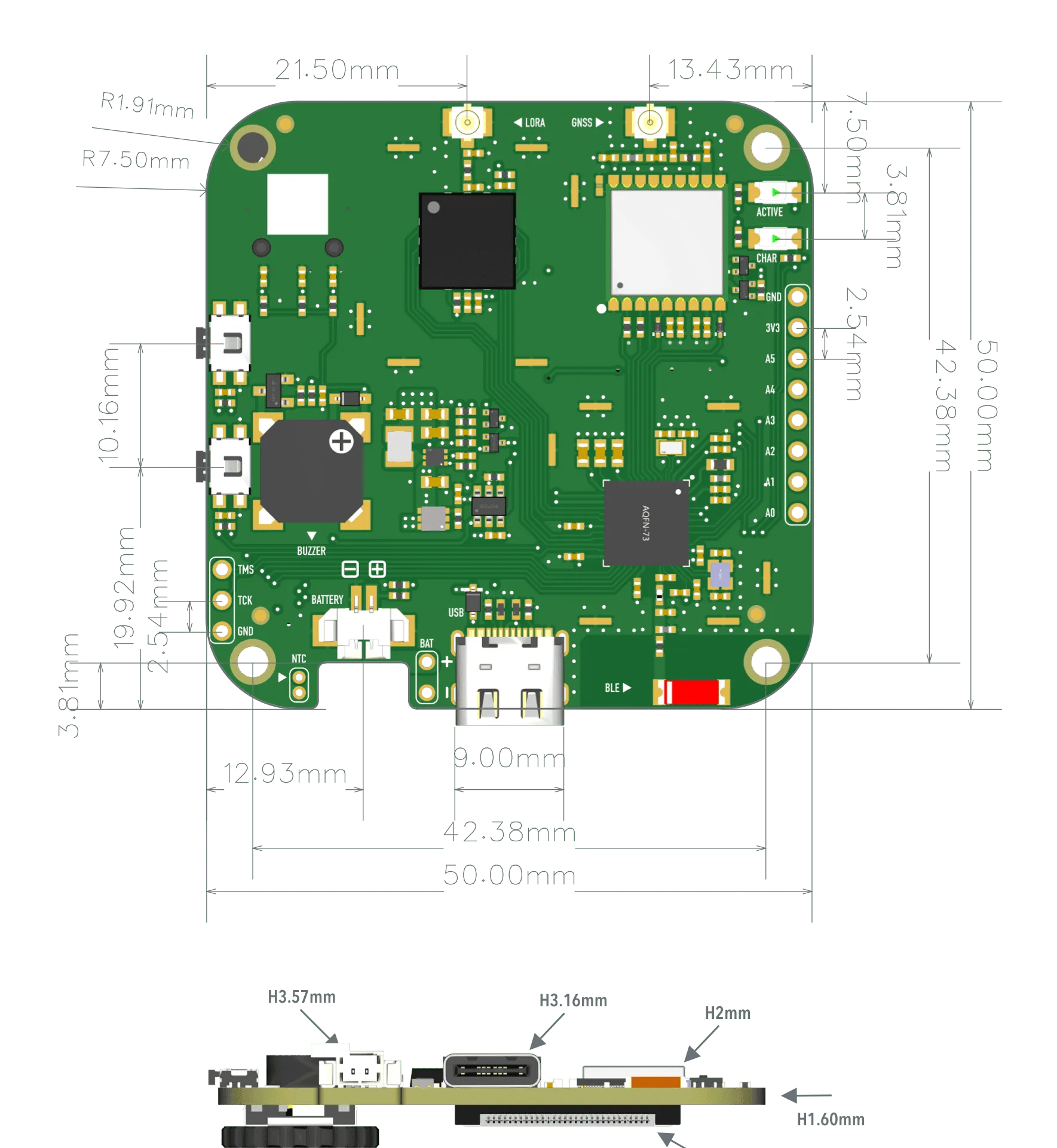
Mechanical dimensions
The FoBE Mesh Tracker C1 PCB measures 50 mm × 50 mm.
Power Supply
USB-C Power
The board can be powered via the USB-C connector (5 V).
Battery charging current is limited to 800 mA.
Battery Power
The board can be powered by a single-cell Li-ion/Li-Po battery connected to the 2-pin MX1.25 battery input interface. The battery voltage range is 3.7 V to 4.2 V.
Peripheral Power Control
GNSS Module
GPS power (GNSS-3V3) is controlled by MCU P0.26. Backup power for GNSS data is not switchable.
Peripheral
The OLED display, buzzer, and MFP (PERI-3V3) are controlled by MCU P0.16.
Status Indicators
The board has two indicator LEDs:
- Power LED
- Charging Indicator LED
Buttons
The board has two buttons:
- Reset Button
- User Button (connected to MCU P1.00)
Battery Management
- The battery charging IC directly manages the battery connection.
- The NTC header is directly connected to the charging IC.
- Battery voltage is measured using a voltage divider (1 MΩ and 1.5 MΩ resistors) and read by MCU P0.05.
Sub-GHz Radio (LoRa)
The FoBE Mesh Tracker C1 board features an on-board sub-GHz radio module based on the Semtech SX1262. It supports LoRa and (G)FSK modulation and operates in the 433 MHz, 868 MHz, or 915 MHz bands (depending on the model). An integrated 1.8 V TCXO ensures excellent stability across temperature variations.
Key specifications include a receive current as low as 4.2 mA, a maximum transmit power of up to +22 dBm, and sensitivity down to -148 dBm, providing excellent interference immunity.
The module connects to the nRF52840 SoC via SPI for long-range wireless communication:
| SX1262 Pin | GPIO Pin |
|---|---|
| MISO | P0.24 |
| MOSI | P0.22 |
| SCK | P0.20 |
| NSS | P1.08 |
| RST | P0.13 |
| BUSY | P0.15 |
| DIO1 | P0.17 |
| RFSW | P0.11 |
GPS
The GPS module has the following pin assignments:
| GPS Pin | GPIO Pin |
|---|---|
| RST | P0.04 |
| RXD | P0.12 |
| TXD | P1.09 |
| PPS | P0.08 |
| WAKE | P0.06 |
Configuration Jumper
The board features a jumper pad:
| Interface | Description |
|---|---|
| CONSTELLATION | Soldering this pad configures the module to use GPS + GLONASS. By default, the pad is not soldered, and the module uses BeiDou + GPS. |
Applications
Meshtastic
Meshtastic is a popular open-source project that allows you to create an off-grid, decentralized mesh network built to run on affordable, low-power devices.
The FoBE Mesh Tracker C1 is compatible with Meshtastic, allowing you to build your own mesh network using this development board.
Get and Flash the latest Meshtastic firmware from the Firmware Hub.
Source code is available on the FoBE Meshtastic Firmware Repository.
MeshCore
MeshCore is a multi platform system for enabling secure text based communications utilising LoRa radio hardware. It can be used for Off-Grid Communication, Emergency Response & Disaster Recovery, Outdoor Activities, Tactical Security including law enforcement and private security and also IoT sensor networks.
The FoBE Mesh Tracker C1 is compatible with MeshCore, allowing you to build your own mesh network using this development board.
Get and Flash the latest MeshCore firmware from the Firmware Hub.
Source code is available on the FoBE MeshCore Firmware Repository.
FAQs
I can't upload firmware to the board, what should I do?
You can try to click the Reset button twice quickly to enter the bootloader mode. If that doesn't work, please check your USB cable and connection.
How do I connect the LoRa and GPS antennas?
The LoRa antenna should be connected to the UF.L connector labeled "LoRa", and the GPS antenna should be connected to the UF.L connector labeled "GPS".
How do I power the board?
You can power the board via the USB-C connector or by connecting a single-cell Li-ion/Li-Po battery to the 2-pin MX1.25 battery input interface.
How do I charge the battery?
When the board is powered via the USB-C connector, the battery will be charged automatically. The charging indicator LED will light up during charging.
How do I update the bootloader?
You can find the bootloader project and instructions in the FoBE Bootloader Repository, please follow the instructions to update the bootloader.
Resources
[PDF] FoBE Mesh Tracker C1 Datasheet
[PDF] FoBE Mesh Tracker C1 Schematic