Quick Start
This guide introduces the FoBE Breakout MFP-HUB and how to use it.
Hardware diagram
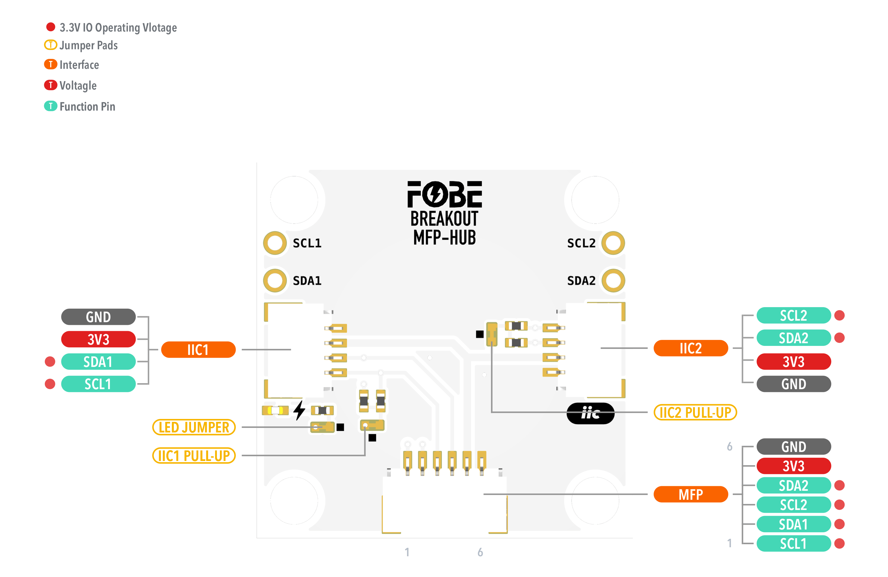
The following figure illustrates the FoBE Breakout MFP-HUB hardware diagram.
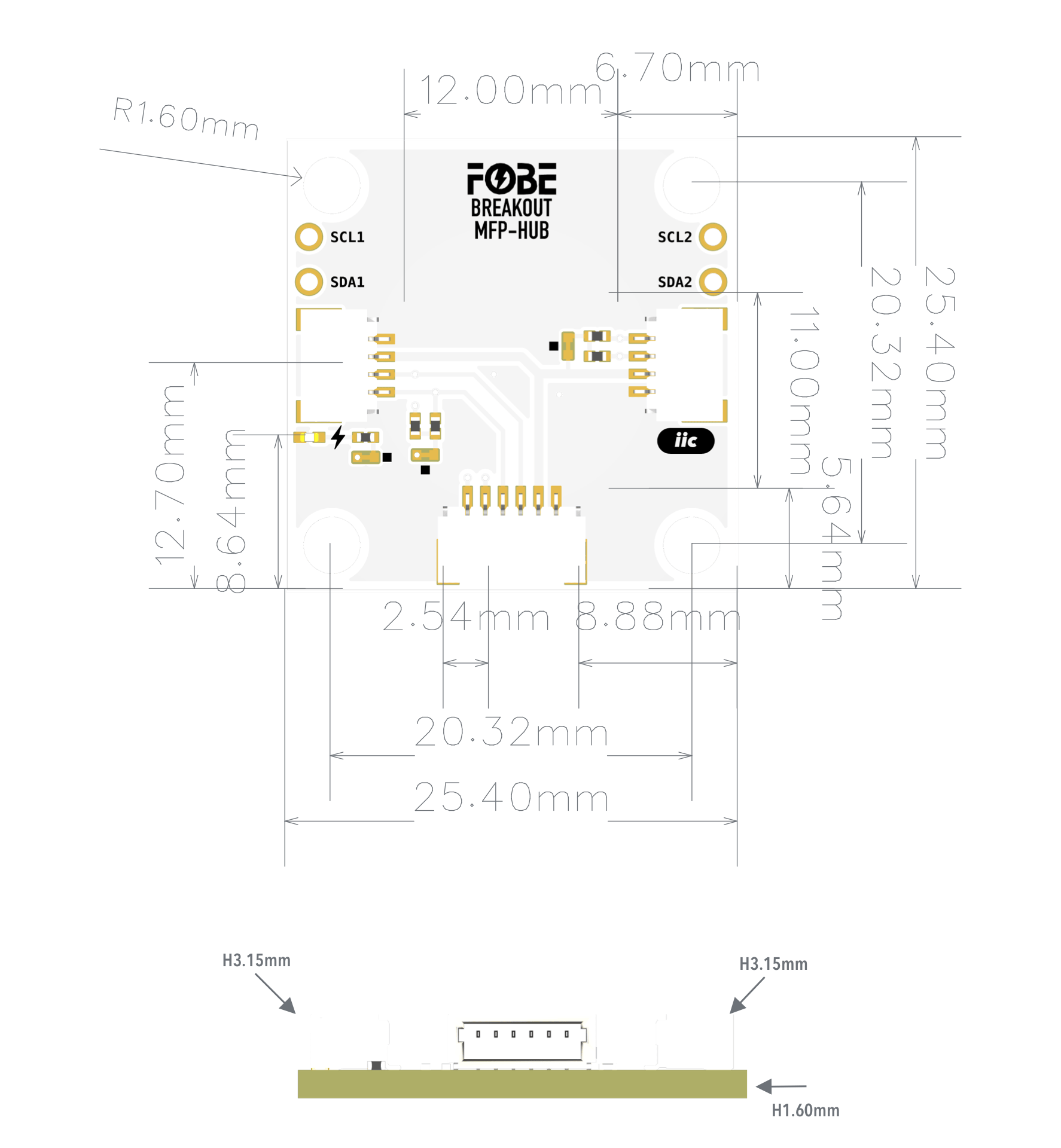
Mechanical dimensions
FoBE Breakout MFP-HUB is a single-sided 25.4mm x 25.4mm (1" x 1") 1.6mm thick PCB. Fixing by 4 x 1.6mm Screw holes.
Interfaces
The module provides one 6-pin MFP connector and two 4-pin I²C connectors.
| 6-Pin MFP (J1) | 4-Pin IIC (J2, J3) | Features |
|---|---|---|
| GND | GND | Ground |
| 3V3 | 3V3 | Power supply |
| SDA2 | SDA2 | I2C2-Data line |
| SCL2 | SCL2 | I2C2-Clock line |
| SDA1 | SDA1 | I2C1-Data line |
| SCL1 | SCL1 | I2C1-Clock line |
Advanced
Jumper
The module features three jumper pads:
| Interface | Description |
|---|---|
| LED-JUMPER | Disconnect this jumper to turn off the power LED for further power saving. |
| IIC1 PULL-UP | Disconnect this jumper to disable the pull-up resistors for the I²C1 port. |
| IIC2 PULL-UP | Disconnect this jumper to disable the pull-up resistors for the I²C2 port. |
Usage Example
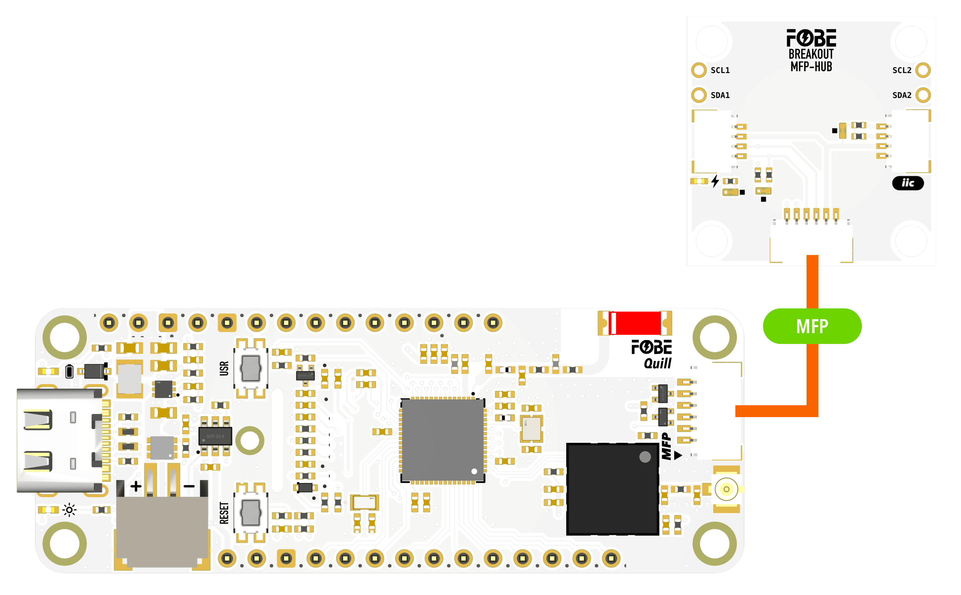
Connection with FoBE Quill and I²C Devices
Connect the FoBE Breakout MFP-HUB to a FoBE Quill board using the MFP cable, and connect two I²C devices to the I²C ports.