Quick Start
This guide introduces the FoBE Breakout L76K and how to use it.
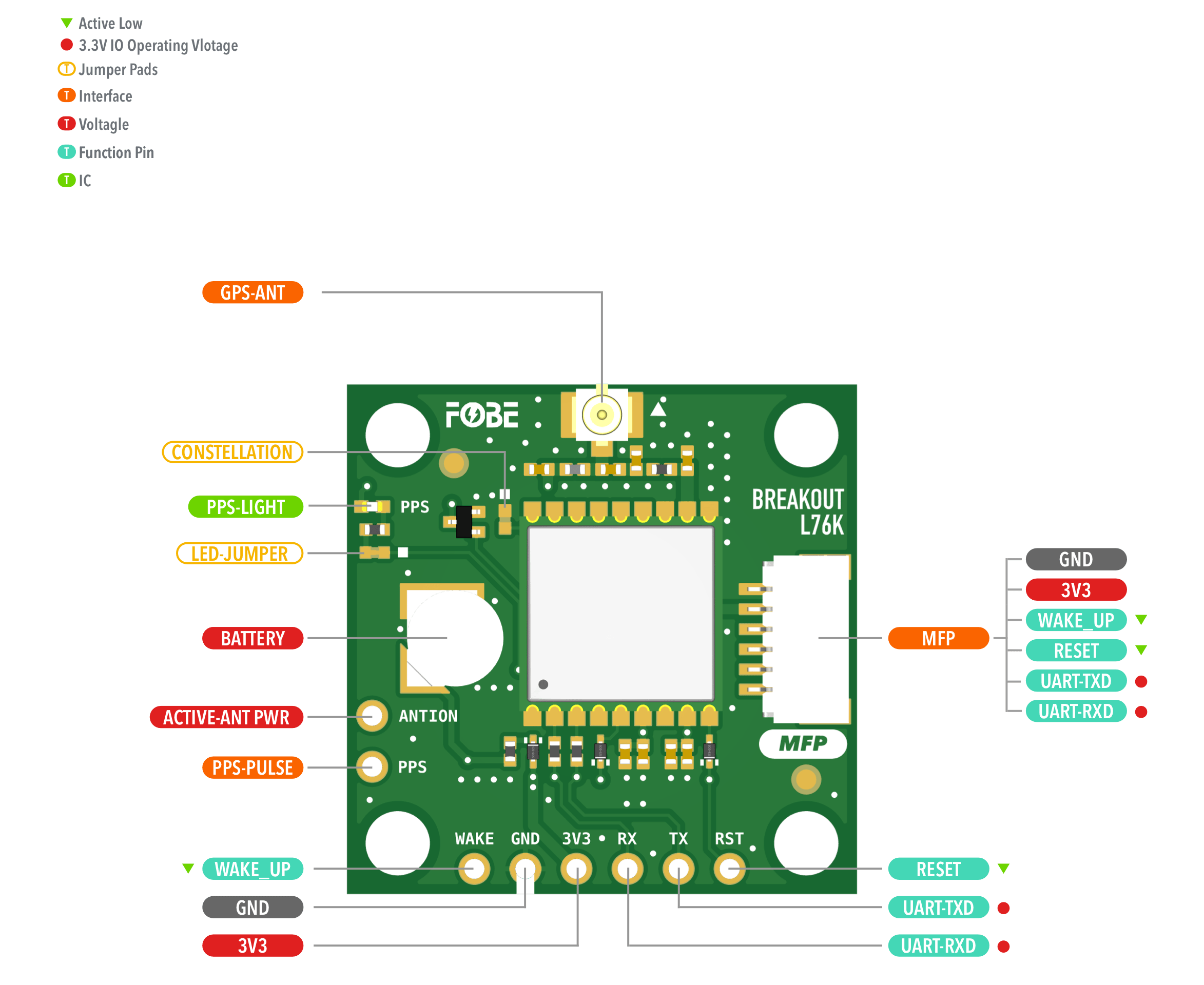
Hardware diagram
The following figure illustrates the FoBE Breakout L76K hardware diagram.
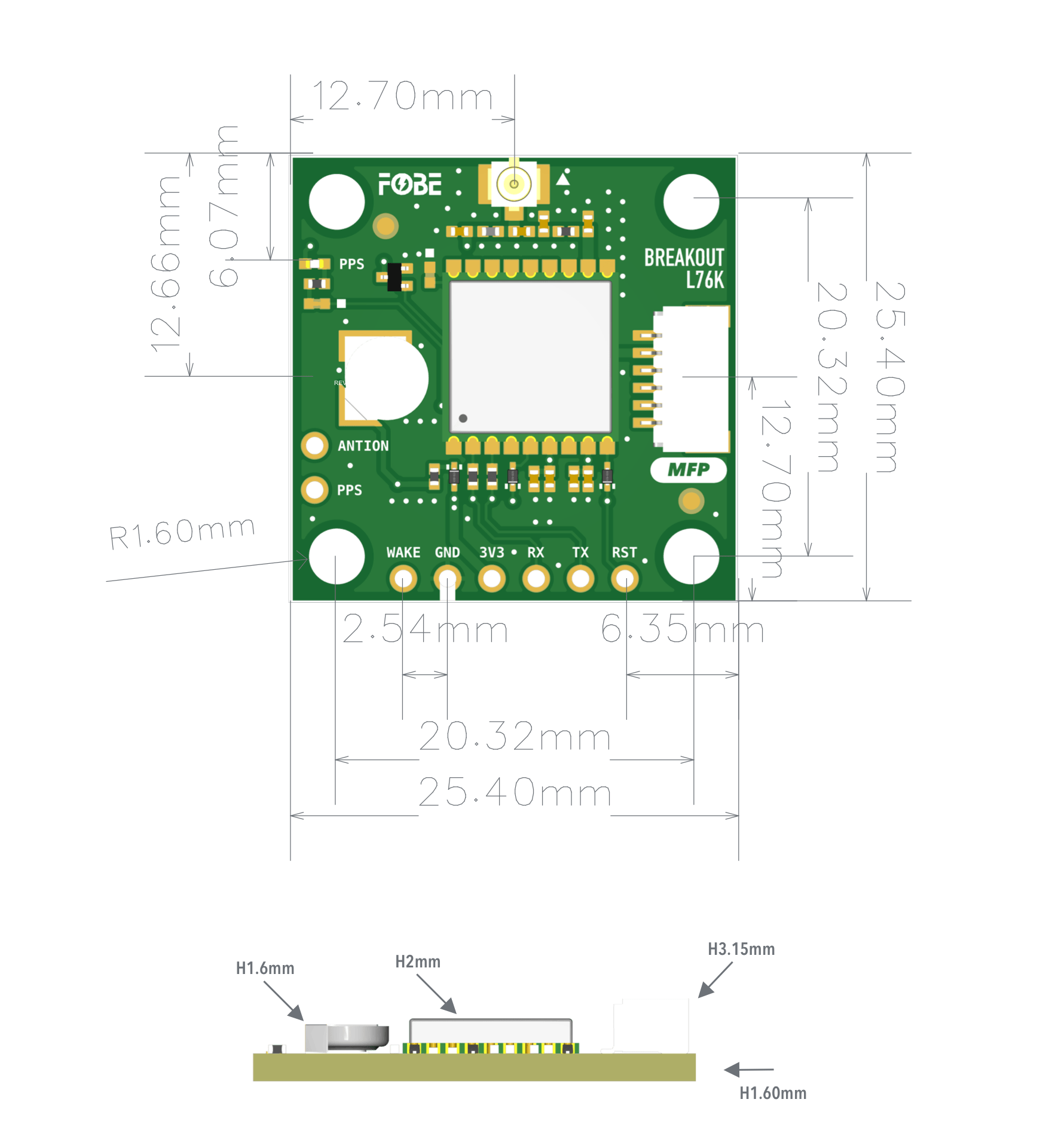
Mechanical dimensions
FoBE Breakout L76K is a single-sided 25.4mm x 25.4mm (1" x 1") 1.6mm thick PCB with a SH1.0 6-pin connector and a set of 6-pin 2.54mm header holes. Fixing by 4 x 1.6mm Screw holes.
Interfaces
The module provides a 6-Pin JST SH1.0 connector and corresponding 2.54mm header holes.
| 2.54mm 6-Pin | JST-SH1.0 | Features |
|---|---|---|
| 3V3 | 3V3 | Power supply, Only 3.3V |
| GND | GND | Ground |
| TX | TX | UART data output |
| RX | RX | UART command input |
| RST | RST | Reset IC, Active Low |
| WAKE | WAKE | Standby mode control, Active Low |
Advanced
Jumper
The module features two jumper pads:
| Interface | Description |
|---|---|
| CONSTELLATION | Satellite constellation selector: Soldered: GPS + GLONASS Open: BeiDou + GPS (Default) |
| LED-JUMPER | Disconnect this jumper to turn off the PPS LED for further power saving |
Additional Features
- Built-in Battery: 3.1V rechargeable button cell for data retention
- Active Antenna Support: Connect "ACTIVE-ANT PWR" pad to 3V3 when using active antenna
- PPS Output: Pulse-per-second signal output, independent of LED jumper control
Programming
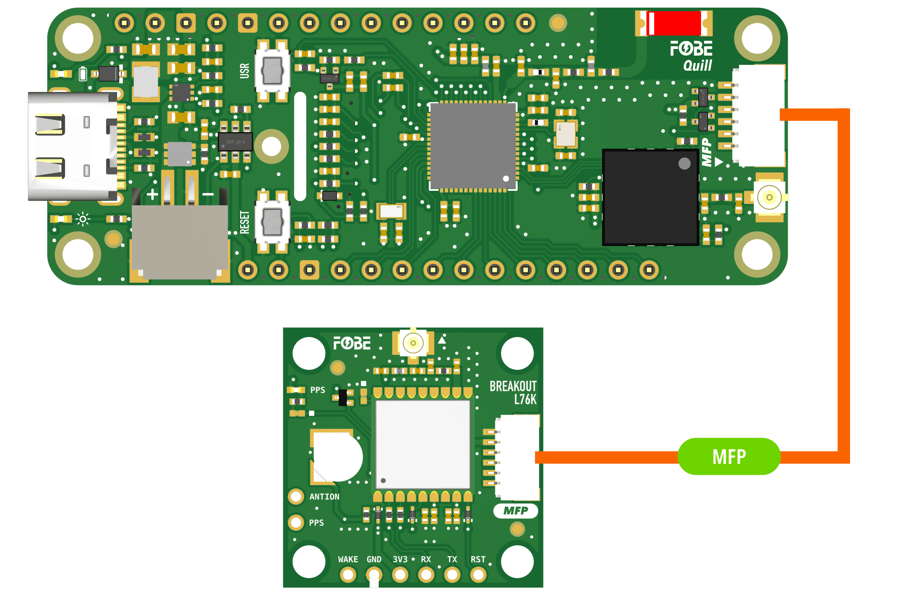
Running with FoBE Quill ESP32S3 Mesh
Let's get started with the FoBE Quill ESP32S3 Mesh using the MFP interface.
- Connect the FoBE Breakout L76K to the FoBE Quill ESP32S3 Mesh using the MFP interface.
-
Create a sketch or PlatformIO project, or follow the FoBE Quill ESP32S3 Programming Guide for pre-configuration.
-
Install the necessary library in your project:
mikalhart/TinyGPSPlus@^1.1.0
- Copy the following code into your sketch or PlatformIO project:
#include <TinyGPSPlus.h>
#include <SoftwareSerial.h>

#define GNSS_BAUD 9600          // GNSS module baud rate
#define GNSS_RX_PIN PIN_MFP1    // RX pin for GNSS communication, change if needed
#define GNSS_TX_PIN PIN_MFP2    // TX pin for GNSS communication, change if needed
#define GNSS_RST_PIN PIN_MFP3   // Reset pin for GNSS, change if needed
#define GNSS_WAKE_PIN PIN_MFP4  // Wake pin for GNSS, change if needed
#define PERI_EN_PIN PIN_PERI_EN // Peripheral enable pin, change if needed

TinyGPSPlus gnss;

// Buffer to store the latest NMEA sentence
String latestNmeaSentence = "";
char nmeaBuffer[128];
int bufferIndex = 0;

// Time tracking variables
unsigned long startupTime = 0;
unsigned long firstFixTime = 0;
bool firstFixAchieved = false;

void setup()
{
  // Initialize serial communication
  Serial.begin(115200);
  Serial.println("Serial initialized");

  // Initialize peripheral power
  if (PERI_EN_PIN >= 0)
  {
    pinMode(PERI_EN_PIN, OUTPUT);
    digitalWrite(PERI_EN_PIN, HIGH); // Enable peripheral power
    Serial.println("Peripheral power enabled");
  }

  // Initialize GNSS module (optional, if you want to test searching time cost)
  pinMode(GNSS_RST_PIN, OUTPUT);
  pinMode(GNSS_WAKE_PIN, OUTPUT);
  digitalWrite(GNSS_RST_PIN, LOW); // Reset the GNSS module
  delay(100);
  digitalWrite(GNSS_RST_PIN, HIGH);  // Release reset
  digitalWrite(GNSS_WAKE_PIN, HIGH); // Wake the GNSS module

  Serial1.begin(GNSS_BAUD, SERIAL_8N1, GNSS_RX_PIN, GNSS_TX_PIN);
  Serial.println("GNSS bus initialized");

  // Wait a moment for module to fully initialize
  delay(200);

  // Record startup time
  startupTime = millis();
  Serial.printf("Startup time recorded: %lu ms\n", startupTime);

  // Wait for GNSS to be ready (equivalent to sensor init loop)
  Serial.println("Waiting for GNSS data...");
  unsigned long startTime = millis();
  while (millis() - startTime < 10000) // Wait up to 10 seconds
  {
    while (Serial1.available() > 0)
    {
      gnss.encode(Serial1.read());
    }
    if (gnss.location.isValid() || gnss.time.isValid() || gnss.satellites.value() > 0)
    {
      break;
    }
    delay(200);
  }

  // Configure GNSS settings, calculate checksum reference https://www.hhhh.org/wiml/proj/nmeaxor.html
  Serial1.write("$PCAS04,7*1E\r\n"); // Configure satellite constellation
  delay(250);
  Serial1.write("$PCAS11,3*1E\r\n"); // Configure positioning mode
  delay(250);
  Serial1.write("$PCAS03,1,0,0,0,1,0,0,0,0,0,,,0,0*02\r\n"); // Configure positioning frequency
  delay(250);
  Serial1.write("$PCAS02,200*1D\r\n"); // Configure positioning frequency
  delay(250);

  Serial.println("GNSS sensor initialized");

  // Start measurement (GNSS automatically starts after initialization)
}

void loop()
{
  delay(50); // Wait equivalent to gnss.wait()

  // Read data from GNSS (equivalent to gnss.update())
  bool dataUpdated = false;
  while (Serial1.available() > 0)
  {
    char c = Serial1.read();

    // Build NMEA sentence buffer
    if (c == '$')
    {
      bufferIndex = 0;
      nmeaBuffer[bufferIndex++] = c;
    }
    else if (bufferIndex > 0 && bufferIndex < 127)
    {
      nmeaBuffer[bufferIndex++] = c;
      if (c == '\n')
      {
        nmeaBuffer[bufferIndex] = '\0';
        latestNmeaSentence = String(nmeaBuffer);
      }
    }

    if (gnss.encode(c))
    {
      dataUpdated = true;
    }
  }

  if (dataUpdated) // Equivalent to gnss.update() == RESULT_OK
  {
    if (gnss.location.isValid() || gnss.time.isValid()) // Equivalent to gnss.hasNewData()
    {
      // Check for first fix achievement
      if (!firstFixAchieved && gnss.location.isValid())
      {
        firstFixTime = millis();
        firstFixAchieved = true;
      }

      // Display data on screen
      Serial.print("\033[H\033[J");
      Serial.println("> FoBE Breakout L76K Monitor");
      Serial.println();
      Serial.print("\033[7m");
      Serial.printf("%-12s%-12s%-12s\n", "INDEX", "VALUE", "UNIT");
      Serial.print("\033[0m");

      if (gnss.location.isValid())
      {
        Serial.printf("%-12s%-12.6f%-12s\n", "LATITUDE", gnss.location.lat(), "°");
        Serial.printf("%-12s%-12.6f%-12s\n", "LONGITUDE", gnss.location.lng(), "°");
      }

      if (gnss.altitude.isValid())
      {
        Serial.printf("%-12s%-12.2f%-12s\n", "ALTITUDE", gnss.altitude.meters(), "m");
      }

      if (gnss.speed.isValid())
      {
        Serial.printf("%-12s%-12.2f%-12s\n", "SPEED", gnss.speed.kmph(), "km/h");
      }

      if (gnss.satellites.isValid())
      {
        Serial.printf("%-12s%-12d%-12s\n", "SATELLITES", gnss.satellites.value(), "");
      }

      if (gnss.hdop.isValid())
      {
        Serial.printf("%-12s%-12.2f%-12s\n", "HDOP", gnss.hdop.hdop(), "");
      }

      // Add GPS time display
      if (gnss.time.isValid() && gnss.date.isValid())
      {
        Serial.printf("%-12s%02d:%02d:%02d%-12s\n", "TIME", gnss.time.hour(), gnss.time.minute(), gnss.time.second(), "UTC");
        Serial.printf("%-12s%04d-%02d-%02d%-12s\n", "DATE", gnss.date.year(), gnss.date.month(), gnss.date.day(), "");
      }

      // Add Time to First Fix Information
      if (firstFixAchieved)
      {
        unsigned long timeToFirstFix = firstFixTime - startupTime;
        Serial.printf("%-12s%-12.3f%-12s\n", "TTFF", timeToFirstFix / 1000.0, "SEC");
      }
      else
      {
        unsigned long currentTime = millis();
        unsigned long timeElapsed = currentTime - startupTime;
        Serial.printf("%-12s%-12.3f%-12s\n", "SEARCHING", timeElapsed / 1000.0, "SEC");
      }

      // Print latest NMEA data stream below the table
      Serial.println();
      Serial.println("Latest NMEA Data Stream:");
      if (latestNmeaSentence.length() > 0)
      {
        Serial.print(latestNmeaSentence);
      }
      else
      {
        Serial.println("No NMEA data received yet");
      }
    }
  }
}
This example code uses ANSI output formatting. Your terminal must support ANSI escape codes to display the output correctly.
# platformio.ini
[env:fobe_quill_esp32s3_mesh]
platform = FoBE Espressif 32
board = fobe_quill_esp32s3_mesh
framework = arduino
lib_deps =
	mikalhart/TinyGPSPlus@^1.1.0
monitor_speed = 115200
monitor_raw = true
- Build and upload the project. You should see the FoBE Breakout L76K Monitor output in the serial monitor (raw mode).
> FoBE Breakout L76K Monitor

INDEX       VALUE       UNIT
LATITUDE    22.123456   °
LONGITUDE   114.123456  °
ALTITUDE    71.20       m
SPEED       17.33       km/h
SATELLITES  15
HDOP        24.80
TIME        19:59:03UTC
DATE        2025-08-08
TTFF        3.236       SEC

Latest NMEA Data Stream:
$GNGSA,A,1,,,,,,,,,,,,,25.5,24.8,25.5,1*0D