Quick Start
This guide introduces the FoBE Quill nRF52840 Mesh and how to use it.
Hardware diagram
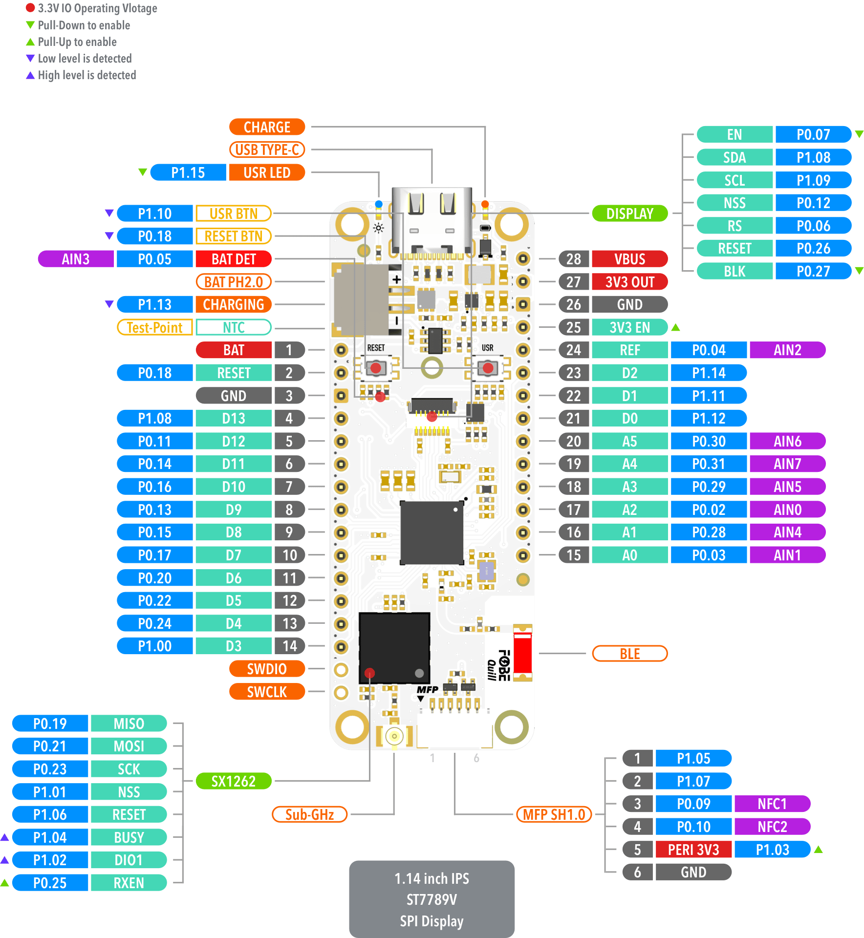
The following figure illustrates the FoBE Quill nRF52840 Mesh hardware diagram.
Mechanical dimensions
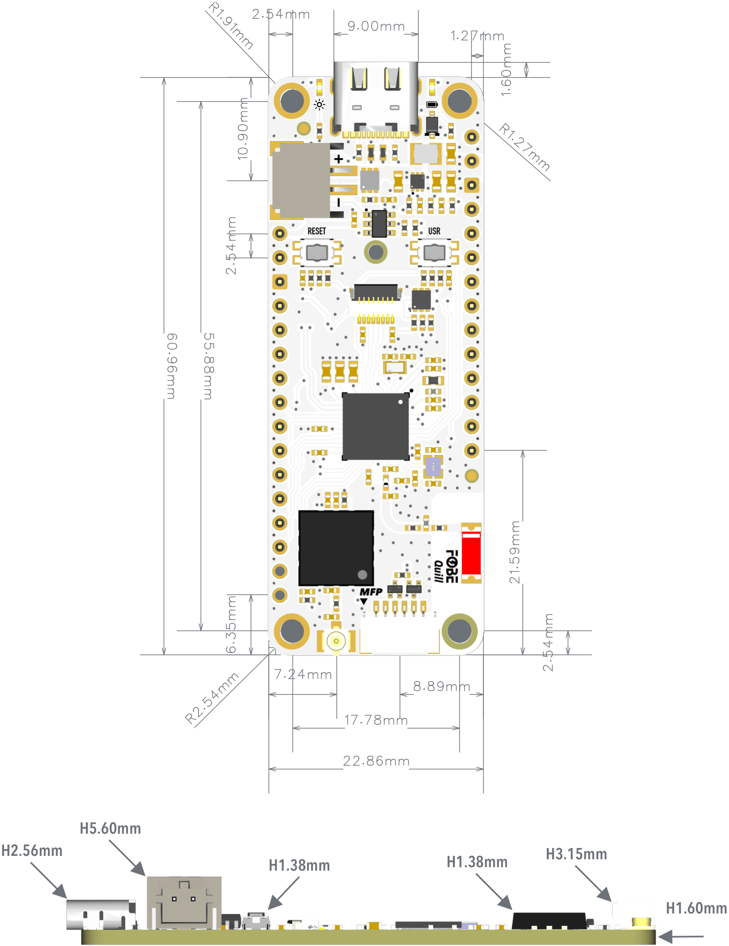
FoBE Quill nRF52840 Mesh is a single-sided 60.96mm x 20.32mm (2.4" x 0.9") 1.6mm thick PCB with a USB Type-C port and dual rows of through-hole pins.
Power supply
The FoBE Quill nRF52840 Mesh is designed to be powered by a battery and includes charging circuitry for lithium batteries. The charger can be powered from a wall adapter via the USB Type-C connector. The incoming USB voltage is routed exclusively to the charger IC, which monitors the battery and stops charging when it's full or if the temperature is too high (this requires soldering a thermistor to the NTC test point). The output from the charger then powers the development kit through a step-down converter.
A high-efficiency step-down converter (TPS62825) with a low quiescent current generates the 3.3V rail. This power supply powers the entire development kit and connected peripheral modules, supporting a maximum current of 2A.
Peripheral Power
PERI_3V3 is a switchable 3.3V power supply that can be controlled by the MCU to cut off power to the MFP (Multi-Function Port) during idle periods, thus saving power. PERI_3V3 is controlled by the P1.03 GPIO on the SoC.
- Set P1.03=1 to turn PERI_3V3 on.
- Set P1.03=0 to turn PERI_3V3 off.
DISPLAY_EN and DISPLAY_BLK are used to control the display power and backlight, respectively. They are controlled by the P0.07 and P0.27 GPIOs on the SoC.
- Set P0.07=0 to turn DISPLAY_EN on.
- Set P0.07=1 to turn DISPLAY_EN off.
- Set P0.27=0 to turn DISPLAY_BLK on.
- Set P0.27=1 to turn DISPLAY_BLK off.
Power consumption
Power consumption measurements were performed while powering the board with a simulated 3.7V lithium battery.
| Mode | Average Current |
|---|---|
| SoC in sleep mode, all peripherals off | < 18uA |
| SoC in active mode, all peripherals on, SX1262 in RX mode | < 40mA |
| SoC in active mode, all peripherals on, SX1262 in TX mode | < 140mA |
Voltage measurement
Battery voltage is measured using a voltage divider with high-precision thick film resistors. The high-side resistor (R1) is 1M Ohm, and the low-side resistor (R2) is 1.5M Ohm. The SoC's P0.05 GPIO is connected to the measurement point.
For a voltage divider circuit with two resistors, R1 and R2, in series, where Vin is the input voltage (battery voltage) and Vout is the voltage across R2 (measured by the ADC):
Vout = Vin * (R2 / (R1 + R2))
In this case: Vout = Vin * (1.5M / (1M + 1.5M)) = Vin * 0.6
Therefore: Vin = Vout / 0.6 = Vout * 1.667
By reading the voltage at the measurement point with the ADC, the battery voltage can be calculated by multiplying the measured voltage by 1.667.
General purpose I/Os
There are up to 20 multi-function General Purpose I/Os (GPIOs) available on the header pins, 6 of which can be used as ADC inputs. These GPIOs operate at a 3.3V logic level. Any GPIO can be mapped to a digital peripheral (such as UART, SPI, TWI, PDM, I2S, QSPI, PWM, and QDEC) for layout flexibility.
The MFP provides an additional 4 GPIO pins. Two of these can be connected to an NFC antenna, used with modules supporting the MFP interface, or configured as two I2C channels.
Display
The FoBE Quill nRF52840 Mesh features an on-board 1.14-inch full-color IPS display, driven by an ST7789V chip and mounted on a PETG bracket. It connects to the development board via an FPC (Flexible Printed Circuit) and has a resolution of 135 x 240 pixels with a maximum brightness of 400 cd/m².
Buttons and LEDs
There are two buttons and one blue LED connected to dedicated GPIOs on the nRF52840 SoC. The following table shows the connections:
| Component | GPIO Pin | Active state |
|---|---|---|
| Reset Button | P0.18 | Low |
| USR Button | P1.10 | Low |
| USR LED | P0.14 | High |
Sub-GHz Radio
The FoBE Quill nRF52840 Mesh board features an on-board sub-GHz radio module based on the Semtech SX1262. It supports LoRa and (G)FSK modulation and operates in the 433 MHz, 868 MHz, and 915 MHz frequency bands (depending on the model). An integrated 1.8V TCXO ensures excellent stability across temperature variations.
Key specifications include a low active receive current of just 4.2 mA, a maximum transmit power of up to +22 dBm, and high sensitivity down to -148 dBm, providing excellent interference immunity.
The module connects to the nRF52840 SoC via SPI for long-range wireless communication:
| SX1262 Pin | GPIO Pin | Active state |
|---|---|---|
| MISO | P0.19 | |
| MOSI | P0.21 | |
| SCK | P0.23 | |
| NSS | P1.01 | Low |
| RST | P1.06 | Low |
| BUSY | P1.04 | High |
| DIO1 | P1.02 | High |
| RXEN | P0.25 | High |
Antenna
Bluetooth and 2.4 GHz Antenna
The FoBE Quill nRF52840 Mesh board has an embedded SMD ceramic antenna for the nRF52840 SoC, which supports Bluetooth and 2.4 GHz communication.
Sub-GHz Antenna
The FoBE Quill nRF52840 Mesh board has an iPEX-U.FL connector for an external sub-GHz antenna.
Debug interface
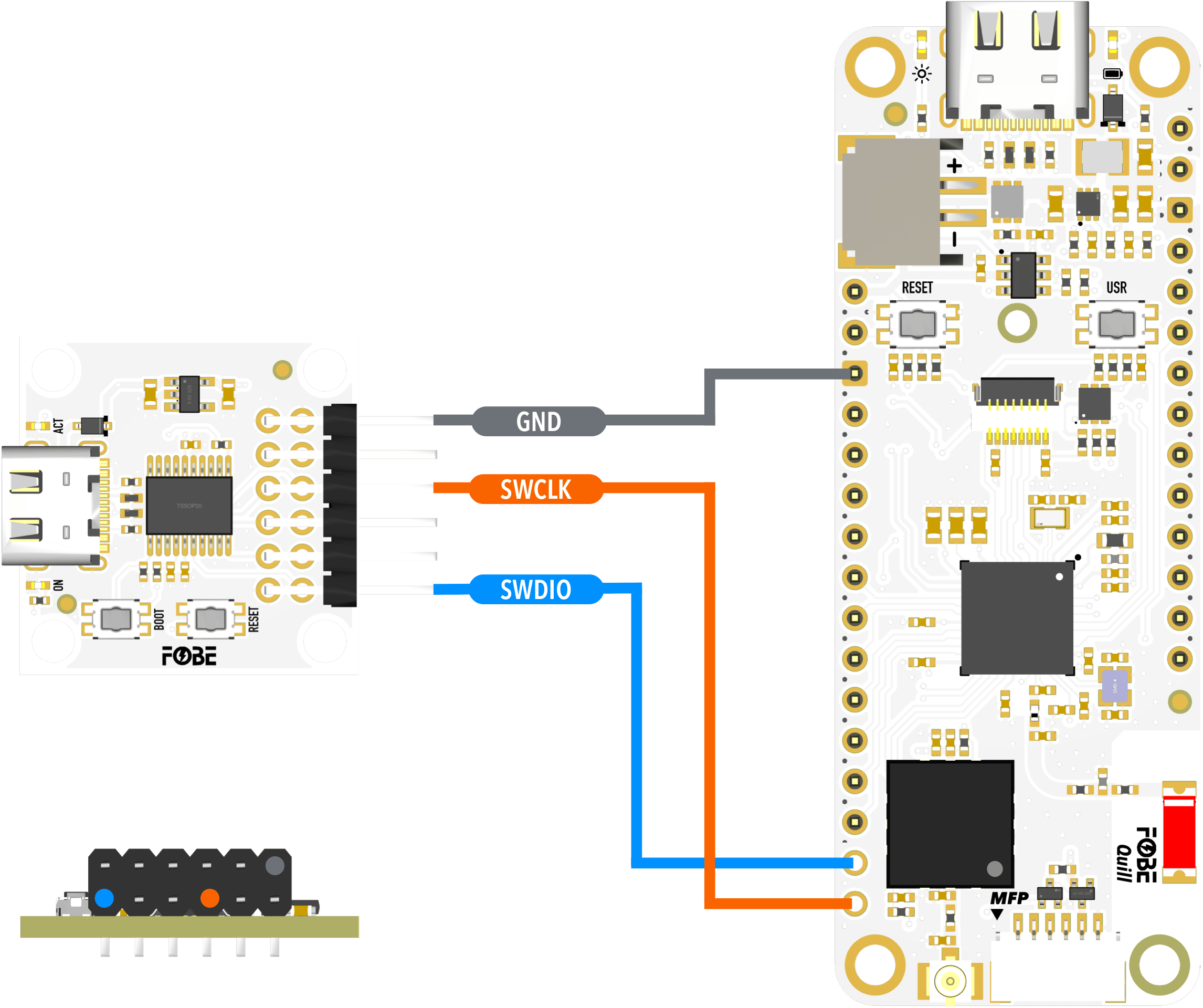
The FoBE Quill nRF52840 Mesh board provides a debug interface via the SWD (Serial Wire Debug) port. This allows developers to program and debug their applications using compatible tools and IDEs.
Light up the board
Prerequisite
Before you begin, please make sure you have the following items:
Hardware
- FoBE Quill nRF52840 Mesh board
- USB-C Cable (must support data transfer)
- 3.7V Li-Ion/LiPo Battery (optional, for battery-powered applications)
- Sub-GHz Antenna (required if your program enables sub-GHz communication to avoid damaging the module)
Software
You can use various IDEs for programming the FoBE Quill nRF52840 Mesh.
Setup the board
Follow these steps to get your FoBE Quill nRF52840 Mesh board up and running:
- Connect the Sub-GHz antenna to the iPEX-U.FL connector on the board (if applicable).
If you are using the Sub-GHz radio, you must connect an appropriate antenna to the iPEX-U.FL connector. Operating the radio without an antenna may cause permanent damage.
- Connect the board to your computer using a USB-C cable.
Ensure your USB cable supports data transfer (USB 2.0 or higher). Charge-only cables will not work.
-
Launch the Arduino IDE.
-
Install the board package.
Follow documentation Platform Arduino to install the FoBE Quill nRF52840 Mesh board package.
-
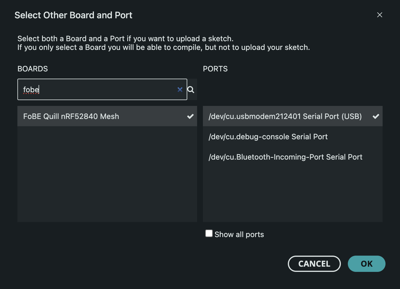
Select the board and port.
- Click the board selector in the top left corner of the Arduino IDE.
- Select the port corresponding to your FoBE Quill nRF52840 Mesh board.
- Select FoBE Quill nRF52840 Mesh from the list of available boards.
-
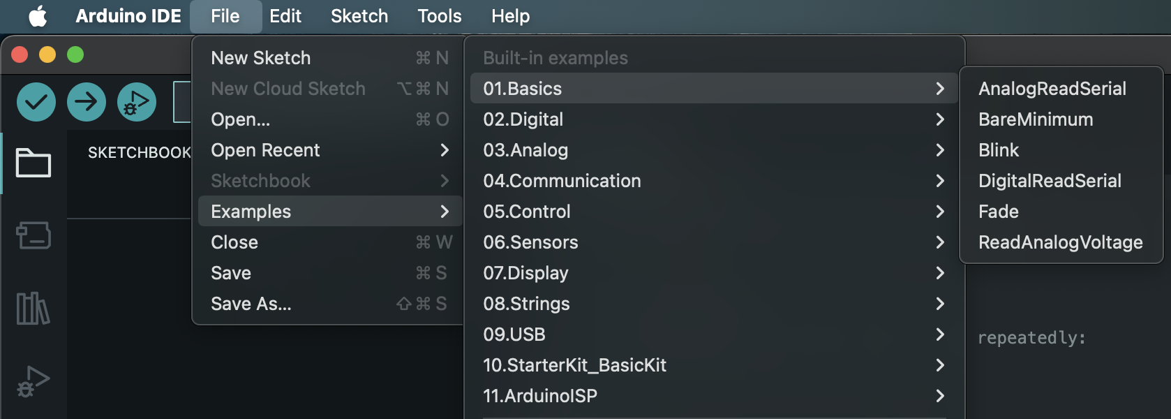
Open an example sketch.
- Navigate to File > Examples > 01.Basics > Blink.
-
Upload the sketch.
- Click the Upload button (right arrow icon) in the Arduino IDE toolbar.
- Wait for the upload process to complete.
If you want to use the USB Serial for printing output, ensure you enable "Serial (CDC)" under Tools > Print Port. Then, add the following line to the top of your sketch:
#include <Adafruit_TinyUSB.h>
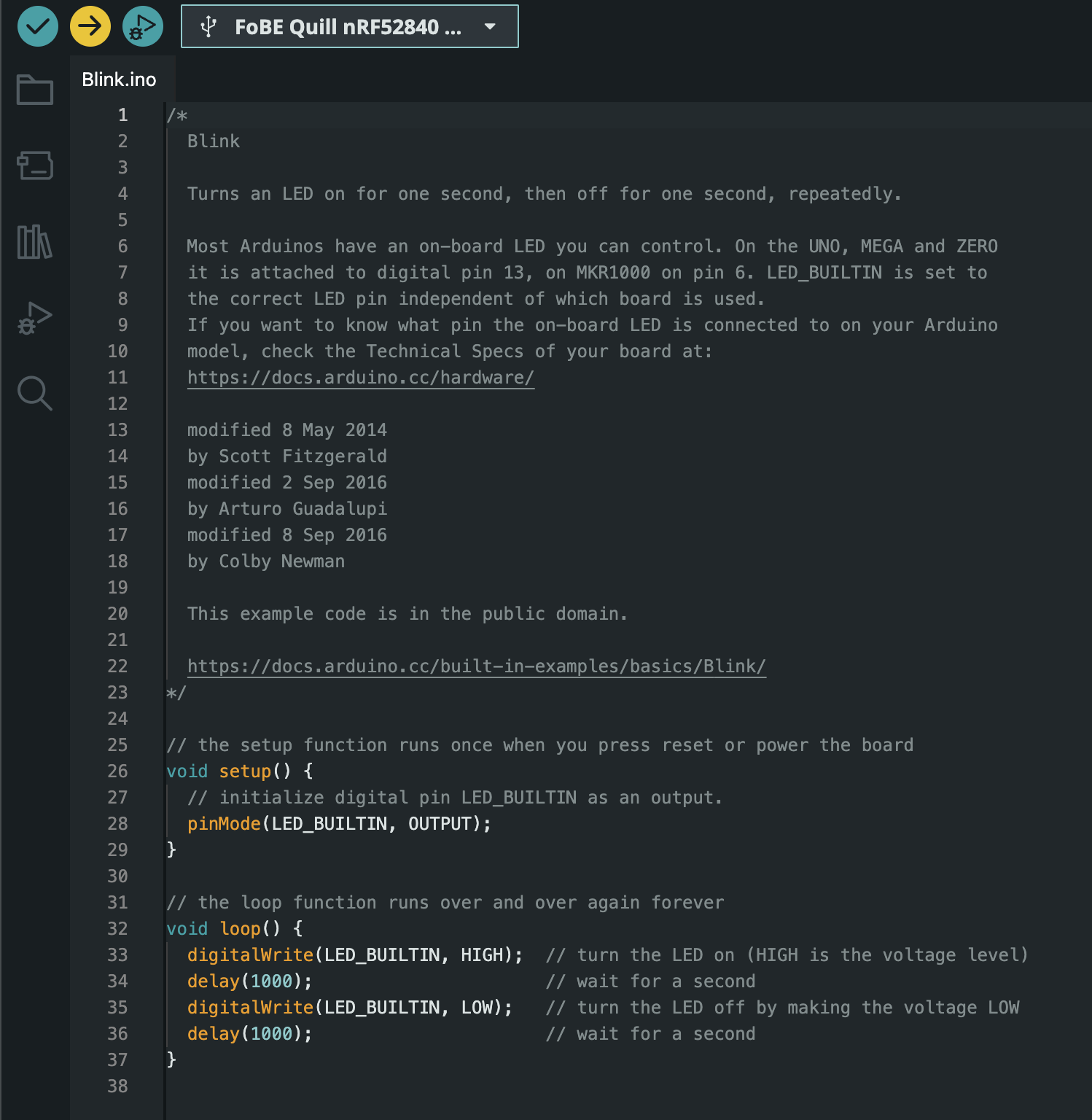
Once the upload is complete, the onboard blue LED should start blinking, indicating that your board is successfully set up and running the example sketch.

Advanced usage
Measuring battery status
The battery voltage can be measured using the ADC (Analog-to-Digital Converter) on the nRF52840 SoC. The measurement is performed through a voltage divider circuit, as described in the Power Supply section.
Measuring battery voltage
#include <Arduino.h>
#include <Adafruit_TinyUSB.h>

void setup()
{
  // Initialize the battery voltage pin
  pinMode(PIN_VBAT, INPUT);
  analogReference(AR_INTERNAL_3_0);
  analogReadResolution(12);

  Serial.begin(115200);
}

void loop()
{
  // Read battery voltage
  int raw = analogRead(PIN_VBAT);
  float vref = 3.0; // ADC reference voltage
  float vmeas = raw * vref / 4095.0; // Measured voltage at ADC pin
  float voltage = vmeas * 1.667; // Calculate actual battery voltage using voltage divider ratio
  Serial.print("Battery voltage: ");
  Serial.print(voltage);
  Serial.println(" V");
  delay(1000);
}
Reading charging status
#include <Arduino.h>
#include <Adafruit_TinyUSB.h>

void setup()
{
  // Initialize the charging pin
  pinMode(PIN_CHARGING, INPUT);
  Serial.begin(115200);
}

void loop()
{
  // Read charging status
  int status = digitalRead(PIN_CHARGING);
  Serial.print("Charging status: ");
  Serial.println(status == LOW ? "Charging" : "Not Charging");
  delay(1000);
}
Drawing on the display
The TFT display on the FoBE Quill nRF52840 Mesh can be controlled using the Adafruit GFX library. You can draw shapes, text, and images on the display.
Make sure to install the Adafruit GFX and Adafruit ST7735 and ST7789 Library libraries in your Arduino IDE before using the following code.
#include <Arduino.h>
#include <Adafruit_TinyUSB.h>
#include <Adafruit_GFX.h>
#include <Adafruit_ST7789.h>
#include <SPI.h>

// Setup ST7789 display
Adafruit_ST7789 tft = Adafruit_ST7789(&SPI1, PIN_ST7789_NSS, PIN_ST7789_RS, PIN_ST7789_RESET);

void setup()
{
  // Initialize the TFT_EN and TFT_BLK pins as outputs
  pinMode(PIN_TFT_EN, OUTPUT);
  pinMode(PIN_TFT_BLK, OUTPUT);

  // Turn on the display power
  digitalWrite(PIN_TFT_EN, LOW);
  // Turn on the backlight
  digitalWrite(PIN_TFT_BLK, LOW);

  // Initialize SPI
  SPI1.begin();
  // Initialize USB Serial
  Serial.begin(115200);

  // Initialize the display
  Serial.println(F("Initializing ST7789 display..."));
  tft.init(135, 240);
  tft.setRotation(1);
  Serial.println(F("Initialized"));

  // Fill the screen with black
  tft.fillScreen(ST77XX_BLACK);
  tft.setTextWrap(false);
  tft.fillScreen(ST77XX_BLACK);
  tft.setCursor(0, 30);
  tft.setTextColor(ST77XX_WHITE);
  tft.setTextSize(2);
  tft.println("Hello FoBE!");

  Serial.println(F("Display update complete"));
}

void loop() {}
Power Consumption Verification
To verify the power consumption of the FoBE Quill nRF52840 Mesh, you can use a power analyzer or a multimeter to measure the current drawn by the board in different modes (e.g., sleep, active).
You can follow the Meshtastic application guide to set up a low-power scenario for measurement.