Getting Started with FoBE Breakout OLED 0.42 inch
Introduction
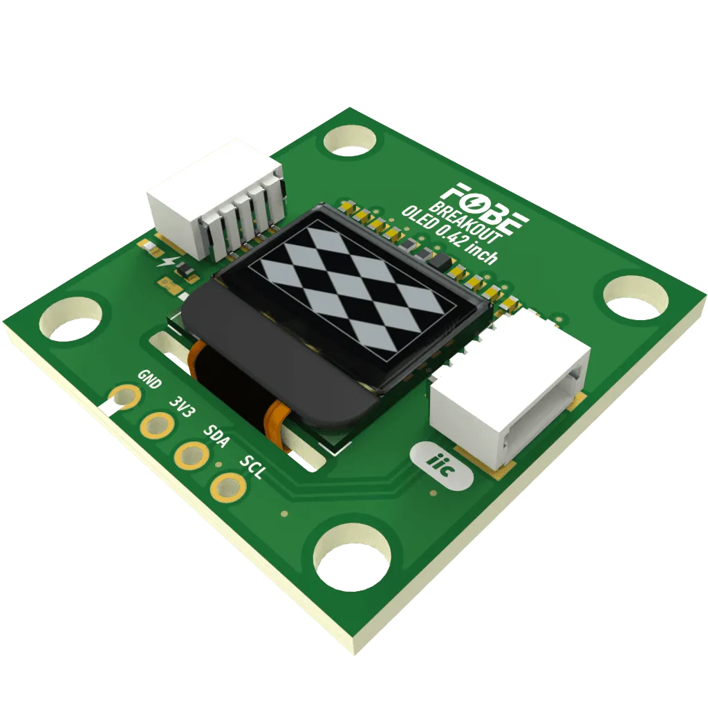
The FoBE Breakout OLED 0.42 inch integrates a 0.42 inch 72x40 pixels graphic monochrome OLED display with the SSD1315 driver IC. This ultra-compact display module is perfect for low-power applications requiring visual feedback. Multiple connectivity options are provided for easy integration into various applications.
Applications
- Electronic Products
- Medical apparatus and equipment
- Traffic Safety
- Wearable devices
Key Features
-
SSD1315
- 0.42 inch PM OLED
- Resolution: 72x40 pixels
- Display color: Monochrome (White)
- Interface: 4-wire I2C
- Operating Temperature: -40 to +85 °C
- Low power consumption
- High contrast ratio
- Wide viewing angle
- Fast response time
-
Connectivity
- MFP-IIC interface (JST-SH1.0 4-Pin)
- 4 x 2.54mm Pin Header
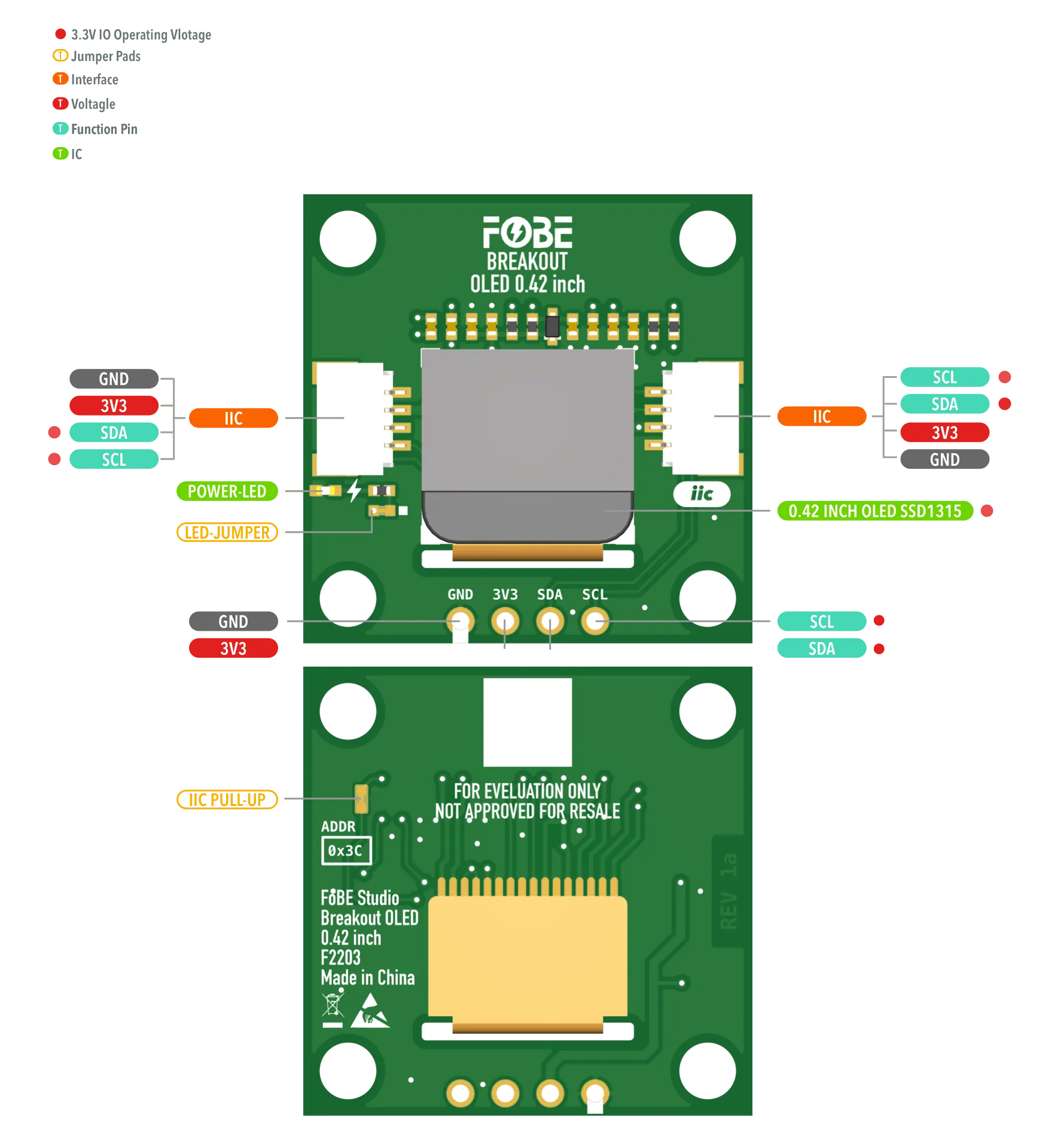
Hardware diagram
The following figure illustrates the FoBE Breakout OLED 0.42 inch hardware diagram.
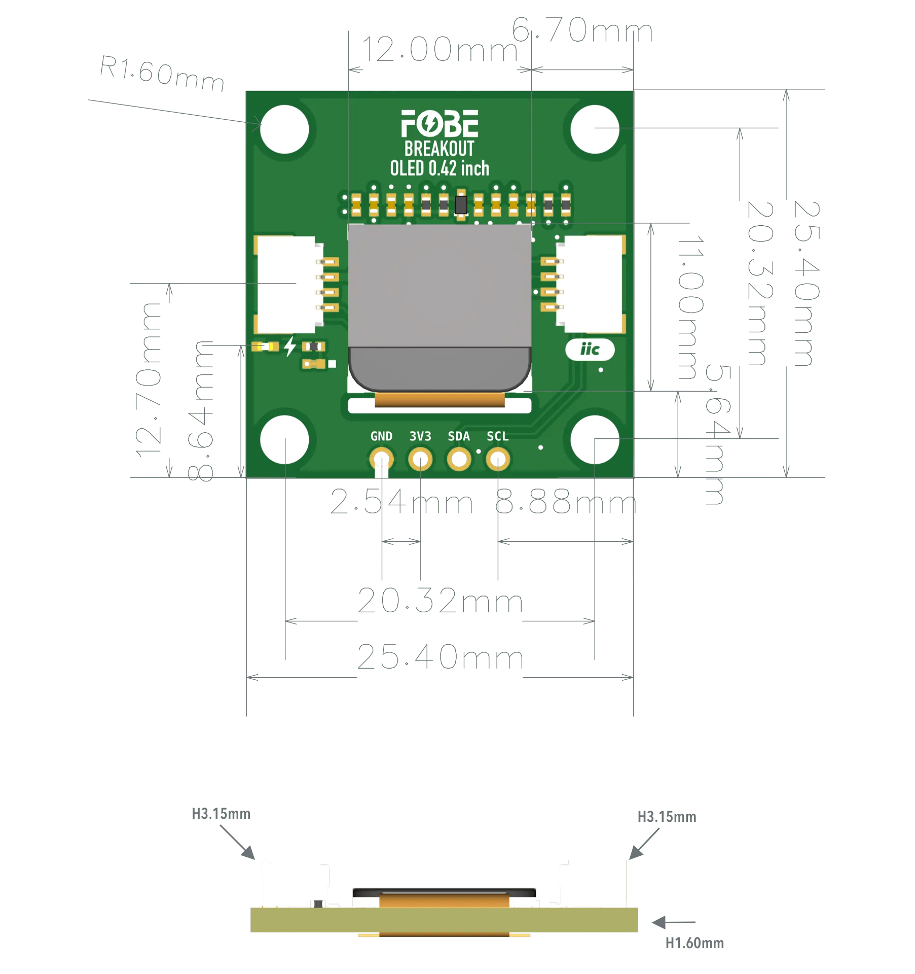
Mechanical dimensions
FoBE Breakout OLED 0.42 inch is a single-sided 25.4mm x 25.4mm (1" x 1") 1.6mm thick PCB with two SH1.0 4-pin connectors and a set of 4-pin 2.54mm header holes. Fixing by 4 x 1.6mm Screw holes.
Interfaces
The module provides dual 4-Pin JST SH1.0 connectors, compatible with STEMMA QT / Qwiic.
| 2.54mm 4-Pin | JST-SH1.0 | Features |
|---|---|---|
| GND | GND | Ground |
| 3V3 | 3V3 | Power supply, Only 3.3V |
| SDA | SDA | I2C-Data line |
| SCL | SCL | I2C-Clock line |
Advanced
Jumper
The module features two jumper pad:
| Interface | Description |
|---|---|
| LED-JUMPER | Disconnect this jumper to turn off the power LED for further power saving |
| IIC PULL-UP | Disconnect this jumper to disable I2C pull-up resistors if external pull-ups are used |
Programming
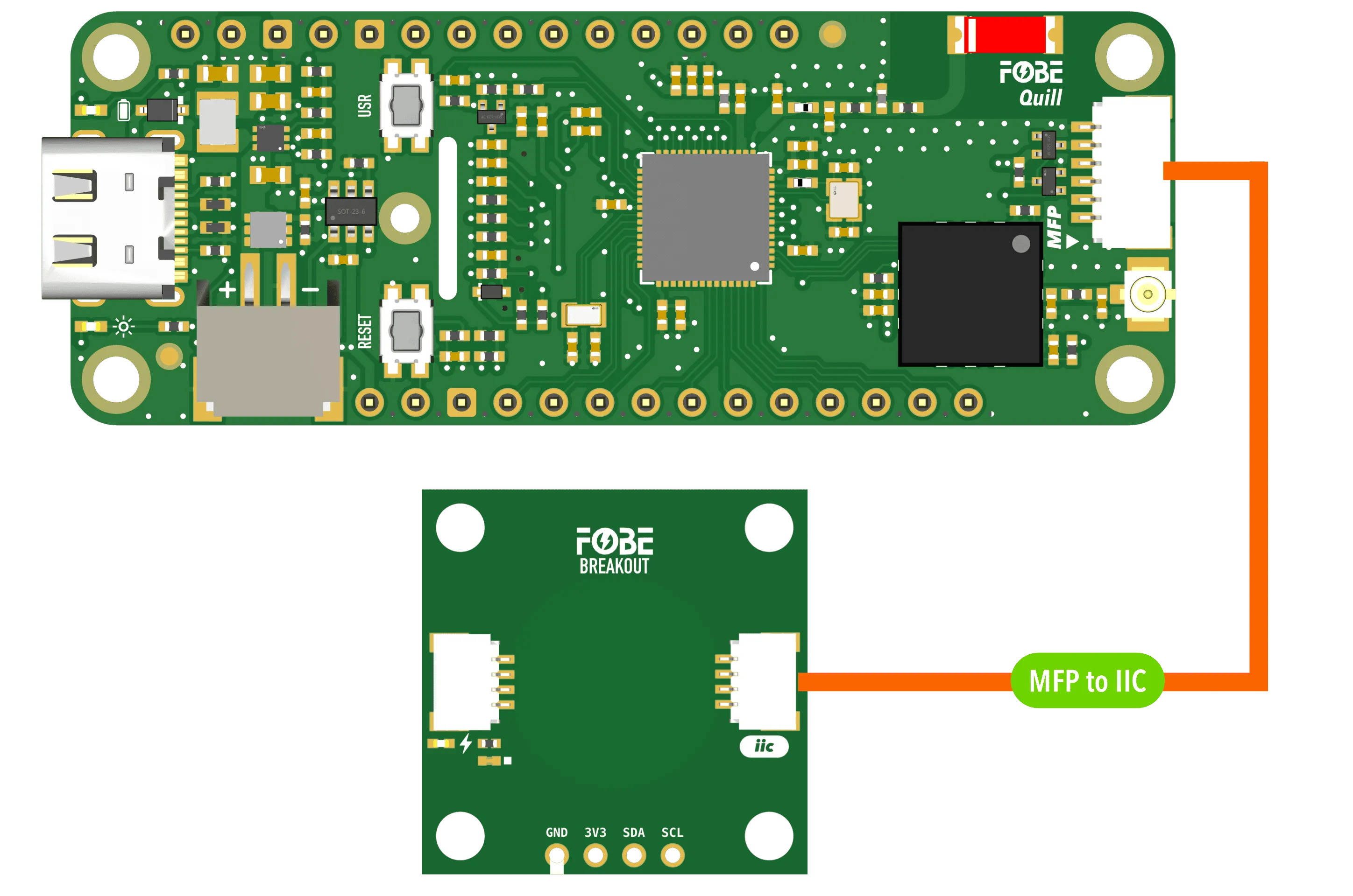
Running with FoBE Quill ESP32S3 Mesh
Let's get started with the FoBE Quill ESP32S3 Mesh using the MFP interface.
- Connect the FoBE Breakout OLED 0.42 inch to the FoBE Quill ESP32S3 Mesh using the MFP interface.
-
Create a sketch or PlatformIO project, or follow the FoBE Quill ESP32S3 Programming Guide for pre-configuration.
-
Install the necessary library in your project:
adafruit/Adafruit SSD1306@^2.5.15
adafruit/Adafruit GFX Library@^1.12.1
- Copy the following code into your sketch or PlatformIO project:
#include <Adafruit_GFX.h>
#include <Adafruit_SSD1306.h>

// Pin definitions
#define I2C_ADDRESS 0x3C        // I2C address for SSD1315 OLED
#define I2C_SDA_PIN PIN_MFP3    // SDA pin for I2C
#define I2C_SCL_PIN PIN_MFP4    // SCL pin for I2C
#define PERI_EN_PIN PIN_PERI_EN // Peripheral enable pin

// Display configuration for SSD1315 72x40 OLED
#define SCREEN_WIDTH 128        // Controller buffer width
#define SCREEN_HEIGHT 64        // Controller buffer height
#define DISPLAY_WIDTH 72        // Actual visible display width
#define DISPLAY_HEIGHT 40       // Actual visible display height
#define X_OFFSET 28            // Horizontal centering offset: (128-72)/2
#define Y_OFFSET 24            // Vertical centering offset: (64-40)/2 + 12
#define OLED_RESET -1          // Reset pin (not used)

TwoWire iic = TwoWire(1);
Adafruit_SSD1306 display(SCREEN_WIDTH, SCREEN_HEIGHT, &iic, OLED_RESET);

// Forward declaration
void showTestPattern();

void setup()
{
  // Initialize serial communication
  Serial.begin(115200);
  Serial.println("SSD1315 OLED Display Example");

  // Enable peripheral power
  if (PERI_EN_PIN >= 0)
  {
    pinMode(PERI_EN_PIN, OUTPUT);
    digitalWrite(PERI_EN_PIN, HIGH);
    Serial.println("Peripheral power enabled");
  }

  // Initialize I2C
  iic.begin(I2C_SDA_PIN, I2C_SCL_PIN);
  delay(200);

  // Initialize SSD1315 display
  Serial.println("Initializing SSD1315 display...");
  if (!display.begin(SSD1306_SWITCHCAPVCC, I2C_ADDRESS))
  {
    Serial.println("SSD1315 initialization failed, trying alternative...");
    if (!display.begin(SSD1306_EXTERNALVCC, I2C_ADDRESS))
    {
      Serial.println("SSD1315 initialization failed completely");
      for (;;); // Stop execution
    }
  }
  Serial.println("SSD1315 display initialized successfully");

  // Configure SSD1315 for 72x40 display
  display.clearDisplay();
  display.setTextWrap(false);

  // SSD1315-specific configuration
  display.ssd1306_command(SSD1306_SETDISPLAYOFFSET);
  display.ssd1306_command(0x00);                       // No hardware offset
  display.ssd1306_command(SSD1306_SETSTARTLINE | 0x0); // Start line 0
  display.ssd1306_command(SSD1306_SEGREMAP | 0x1);     // Column address remapping
  display.ssd1306_command(SSD1306_COMSCANDEC);         // COM scan direction
  display.ssd1306_command(SSD1306_SETCOMPINS);
  display.ssd1306_command(0x12);                       // COM pins configuration for 72x40
  display.ssd1306_command(SSD1306_SETCONTRAST);
  display.ssd1306_command(0x8F);                       // Set contrast
  display.ssd1306_command(SSD1306_MEMORYMODE);
  display.ssd1306_command(0x00);                       // Horizontal addressing mode

  // Display test pattern
  showTestPattern();
}

void showTestPattern()
{
  display.clearDisplay();

  // Draw border for the visible display area
  display.drawRect(X_OFFSET, Y_OFFSET, DISPLAY_WIDTH, DISPLAY_HEIGHT, SSD1306_WHITE);

  // Draw corner markers to verify orientation
  display.drawPixel(X_OFFSET + 1, Y_OFFSET + 1, SSD1306_WHITE);           // Top-left
  display.drawPixel(X_OFFSET + DISPLAY_WIDTH - 2, Y_OFFSET + 1, SSD1306_WHITE);    // Top-right
  display.drawPixel(X_OFFSET + 1, Y_OFFSET + DISPLAY_HEIGHT - 2, SSD1306_WHITE);  // Bottom-left
  display.drawPixel(X_OFFSET + DISPLAY_WIDTH - 2, Y_OFFSET + DISPLAY_HEIGHT - 2, SSD1306_WHITE); // Bottom-right

  // Add corner labels
  display.setTextSize(1);
  display.setTextColor(SSD1306_WHITE);
  display.setCursor(X_OFFSET + 2, Y_OFFSET + 2);
  display.print("TL");
  display.setCursor(X_OFFSET + 56, Y_OFFSET + 2);
  display.print("TR");
  display.setCursor(X_OFFSET + 2, Y_OFFSET + 30);
  display.print("BL");
  display.setCursor(X_OFFSET + 56, Y_OFFSET + 30);
  display.print("BR");

  // Center text showing resolution
  display.setCursor(X_OFFSET + 20, Y_OFFSET + 16);
  display.print("72x40");

  display.display();
  Serial.println("Test pattern displayed successfully");
}

void loop()
{
  // Main loop - add your application code here
}
- Build and upload the project. You should see the text on display.
Resources
[PDF] FoBE Breakout OLED 0.42 inch Datasheet
[PDF] FoBE Breakout OLED 0.42 inch Schematic