Getting Started with FoBE Breakout BM8563
Introduction
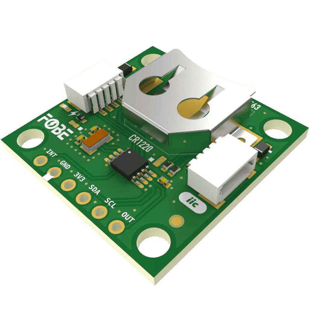
The FoBE Breakout BM8563 integrates the GATEMODE BM8563 real-time clock/calendar IC, providing complete date and time information with automatic calendar calculations including leap years. The clock operates in both 12-hour and 24-hour modes with full binary-coded decimal (BCD) format. Multiple connectivity options are provided for easy integration into various applications.
Applications
- Security access controllers and door controllers
- Time recorders and attendance systems
- IC water-flow meters and gas meters
Key Features
-
BM8563
- Provides year, month, day, weekday, hours, minutes and seconds information
- Century flag for extended date range
- Ultra-low power consumption: 0.25μA at VDD = 3.0V
- I²C interface with slave address: Read A3H and Write A2H
- Programmable clock output (32.768kHz, 1024Hz, 32Hz and 1Hz)
- Alarm and timer functions
- Built-in power voltage detecting circuit
- Open-drain interrupt pin
- Automatic leap year compensation
-
Connectivity
- MFP-IIC interface (JST-SH1.0 4-Pin)
- 6 x 2.54mm Pin Header
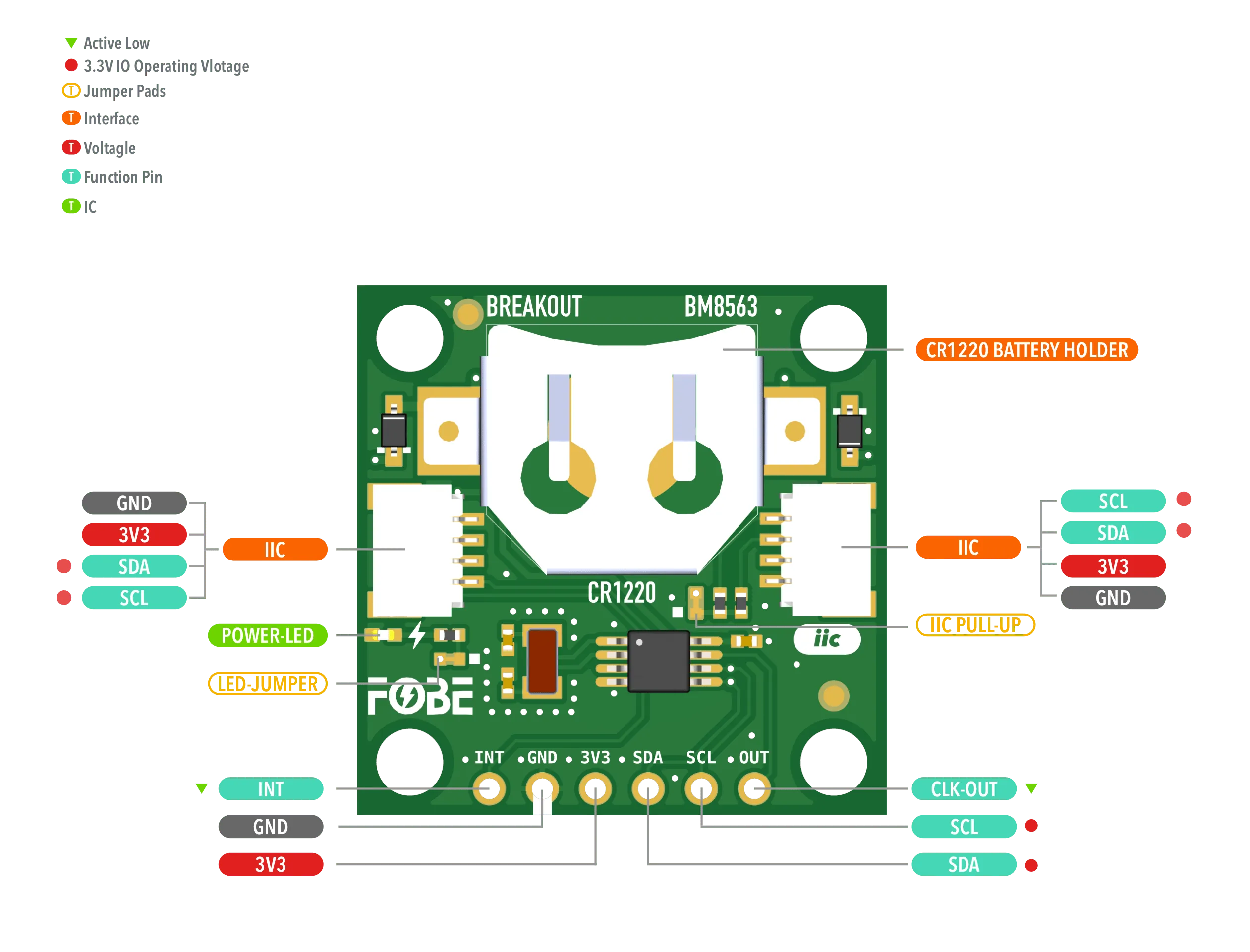
Hardware diagram
The following figure illustrates the FoBE Breakout BM8563 hardware diagram.
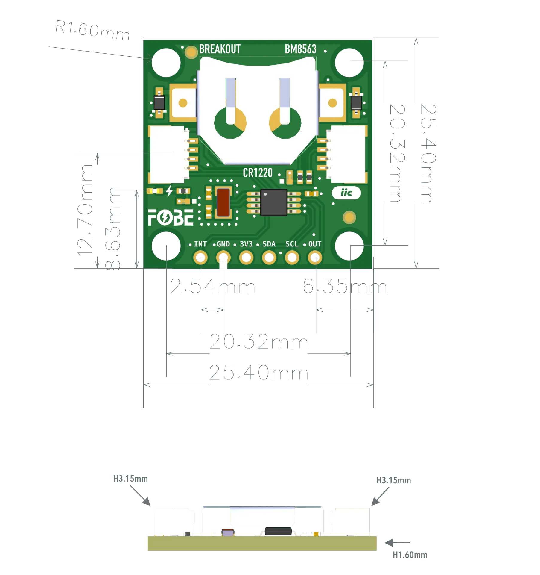
Mechanical dimensions
FoBE Breakout BM8563 is a single-sided 25.4mm x 25.4mm (1" x 1") 1.6mm thick PCB with two SH1.0 4-pin connectors and a set of 6-pin 2.54mm header holes. Fixing by 6 x 1.6mm Screw holes.
Interfaces
The module provides dual 4-Pin JST SH1.0 connectors, compatible with STEMMA QT / Qwiic.
| 2.54mm 6-Pin | JST-SH1.0 | Features |
|---|---|---|
| INT | — | Interrupt, Active Low |
| GND | GND | Ground |
| 3V3 | 3V3 | Power supply, Only 3.3V |
| SDA | SDA | I2C-Data line |
| SCL | SCL | I2C-Clock line |
| OUT | — | Clock output, programmable frequency |
Backup Power
The FoBE Breakout BM8563 module can be powered by a backup battery (CR1220). The backup power supply ensures that the real-time clock continues to keep time even when the main power is disconnected.
Advanced
Jumper
The module features two jumper pads:
| Interface | Description |
|---|---|
| LED-JUMPER | Disconnect this jumper to turn off the power LED for further power saving |
| IIC PULL-UP | Disconnect this jumper to disable I2C pull-up resistors if external pull-ups are used |
Programming
Running with FoBE Quill ESP32S3 Mesh
Let's get started with the FoBE Quill ESP32S3 Mesh using the MFP interface.
- Connect the FoBE Breakout BM8563 to the FoBE Quill ESP32S3 Mesh using the MFP interface.
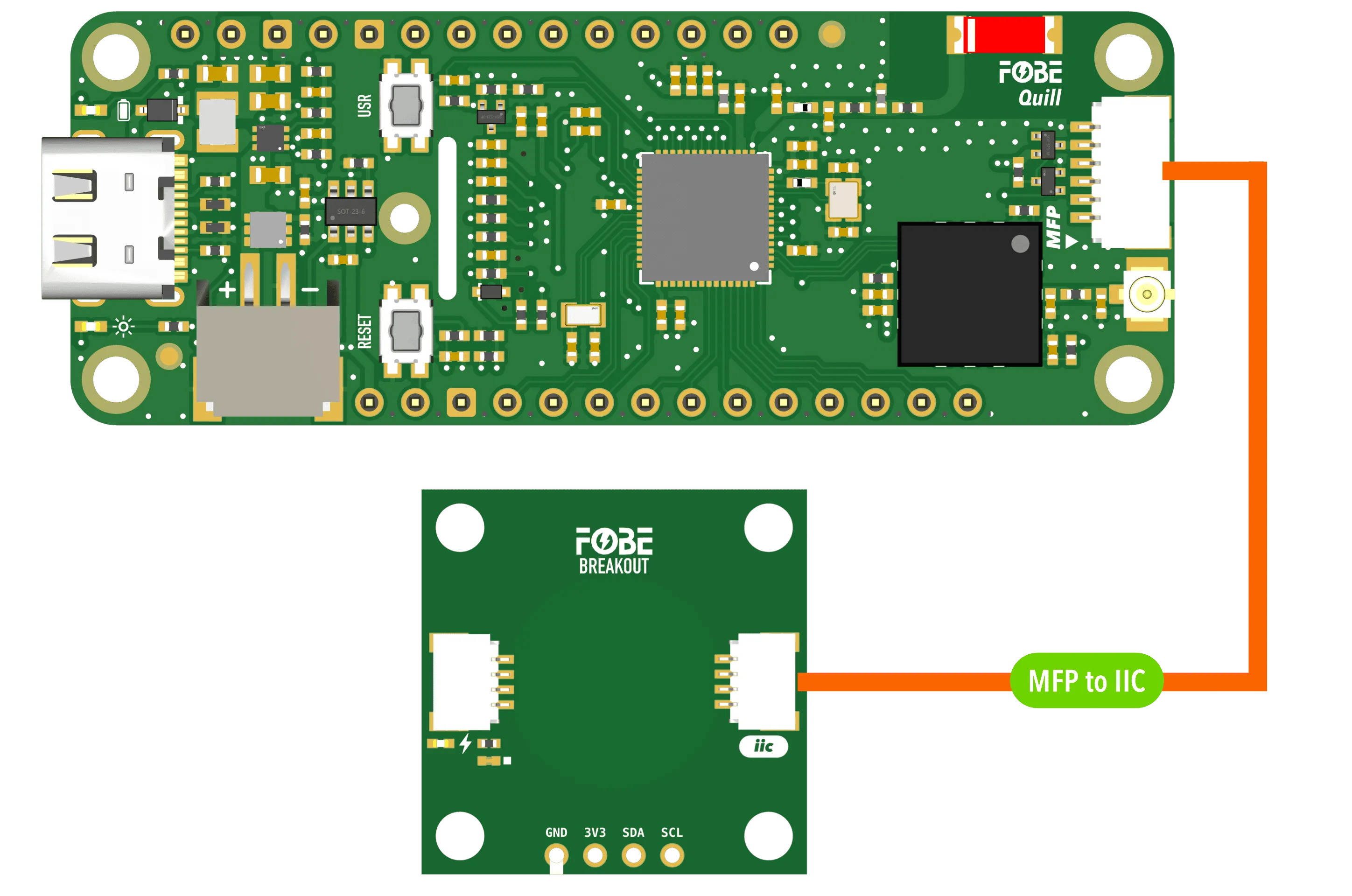
-
Create a sketch or PlatformIO project, or follow the FoBE Quill ESP32S3 Programming Guide for pre-configuration.
-
Install the necessary library in your project:
makuna/RTC@^2.5.0
- Copy the following code into your sketch or PlatformIO project:
#include <RtcPCF8563.h>
#include <Wire.h>

#define I2C_SDA_PIN PIN_MFP3    // SDA pin for MFP to I2C cable, change if needed
#define I2C_SCL_PIN PIN_MFP4    // SCL pin for MFP to I2C cable, change if needed
#define PERI_EN_PIN PIN_PERI_EN // Peripheral enable pin, change if needed

RtcPCF8563<TwoWire> rtcSensor(Wire);

void setup()
{
  // Initialize serial communication
  Serial.begin(115200);
  Serial.println("Serial initialized");

  // Initialize peripheral power
  if (PERI_EN_PIN >= 0)
  {
    pinMode(PERI_EN_PIN, OUTPUT);
    digitalWrite(PERI_EN_PIN, HIGH); // Enable peripheral power
    Serial.println("Peripheral power enabled");
  }

  // Initialize I2C bus
  Wire.begin(I2C_SDA_PIN, I2C_SCL_PIN);
  rtcSensor.Begin();
  Serial.println("I2C bus initialized");

  // Initialize RTC sensor
#if defined(WIRE_HAS_TIMEOUT)
  Wire.setWireTimeout(3000 /* us */, true /* reset_on_timeout */);
#endif
  Serial.println("BM8563 RTC sensor initialized");

  // Configure RTC if needed
  RtcDateTime compiled = RtcDateTime(__DATE__, __TIME__);
  if (!rtcSensor.IsDateTimeValid() || rtcSensor.GetDateTime() < compiled)
  {
    rtcSensor.SetDateTime(compiled);
  }

  if (!rtcSensor.GetIsRunning())
  {
    rtcSensor.SetIsRunning(true);
  }

  // Clear alarms and timers
  rtcSensor.StopAlarm();
  rtcSensor.StopTimer();
  rtcSensor.SetSquareWavePin(PCF8563SquareWavePinMode_None);
}

void loop()
{
  delay(1000); // Wait 1 second between readings

  if (rtcSensor.IsDateTimeValid())
  {
    RtcDateTime now = rtcSensor.GetDateTime();

    // Display data on screen
    Serial.print("\033[H\033[J");
    Serial.println("> FoBE Breakout BM8563 RTC Monitor");
    Serial.println();
    Serial.print("\033[7m");
    Serial.printf("%-12s%-12s\n", "INDEX", "VALUE");
    Serial.print("\033[0m");
    Serial.printf("%-12s%02u/%02u/%04u\n", "Date", now.Month(), now.Day(), now.Year());
    Serial.printf("%-12s%02u:%02u:%02u\n", "Time", now.Hour(), now.Minute(), now.Second());
    Serial.printf("%-12s%-12s\n", "Status", rtcSensor.GetIsRunning() ? "Running" : "Stopped");
    Serial.printf("%-12s%-12s\n", "Valid", rtcSensor.IsDateTimeValid() ? "Yes" : "No");
  }
}
This example code uses ANSI output formatting. Your terminal must support ANSI escape codes to display the output correctly.
# platformio.ini
[env:fobe_quill_esp32s3_mesh]
platform = FoBE Espressif 32
board = fobe_quill_esp32s3_mesh
framework = arduino
lib_deps =
	makuna/RTC@^2.5.0
monitor_speed = 115200
monitor_raw = true
- Build and upload the project. You should see the FoBE Breakout BM8563 Monitor output in the serial monitor (raw mode).
> FoBE Breakout BM8563 RTC Monitor

INDEX       VALUE
Date        08/09/2025
Time        02:04:48
Status      Running
Valid       Yes
Resources
[PDF] FoBE Breakout BM8563 Datasheet
[PDF] FoBE Breakout BM8563 Schematic
[PDF] FoBE Breakout BM8563 Dimension